Digital hourglass
Unlike most ordinary kitchen timers this digital hourglass is gesture
controlled and uses six LED rings instead of an LC display. Originally the
project was part of a university course “embedded systems”, but in the end
it took two years – way more than one semester – until it reached its current
state.
Currently the project lacks a catchy name. Its internal name is “sanduhr”
(hourglass) due to its user interface and the yellow LEDs used. Some people
refer to it as “egg timer” or “iUhr”, which sounds like “Ei(er)uhr” (egg timer)
in German.
Usage
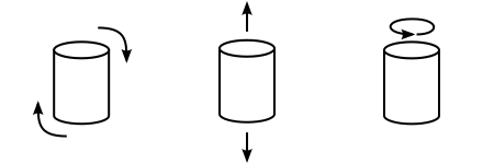
The device is controlled with three gestures: Flip, shake and spin.
When idle shaking once starts the time selection mode. First a coarse
selection in steps of 10 minutes is performed by spinning the device. After a
second shake up to five minutes can be added or subtracted, depending on the
spin direction. The maximum time is 65 minutes. Flipping the device starts and
stops the timer. The user is notified upon timer expiration by flashing LEDs
and a short beep tone.
Hardware
The device consists of two different boards: The first one holds three LEDs
each and the other one control logic and a speaker. Altium design files are
available here (signature). Reading the errata before using them is
highly recommended.
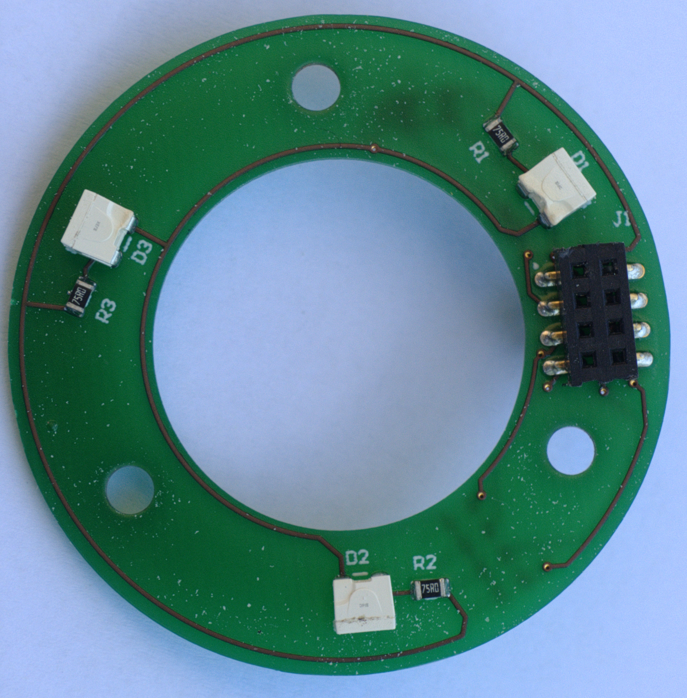
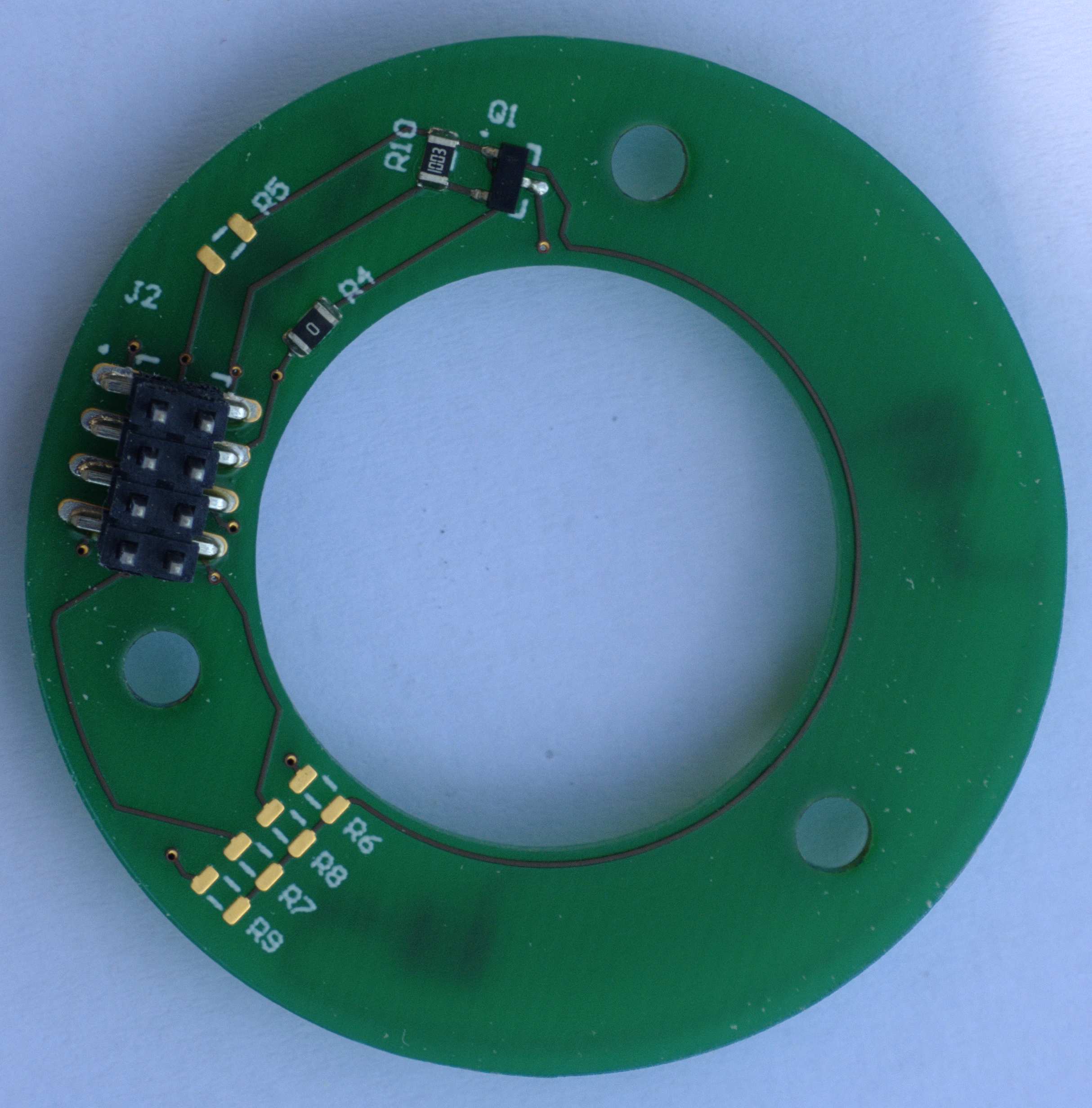
LED board
This is the LED board. It is equipped with three side LEDs from Osram. R4–R9
connect one of the input lines of J1 and J2 to the transistor Q1 with a 0 Ω
resistor. Thus the same, configurable board can be used for all six rings.
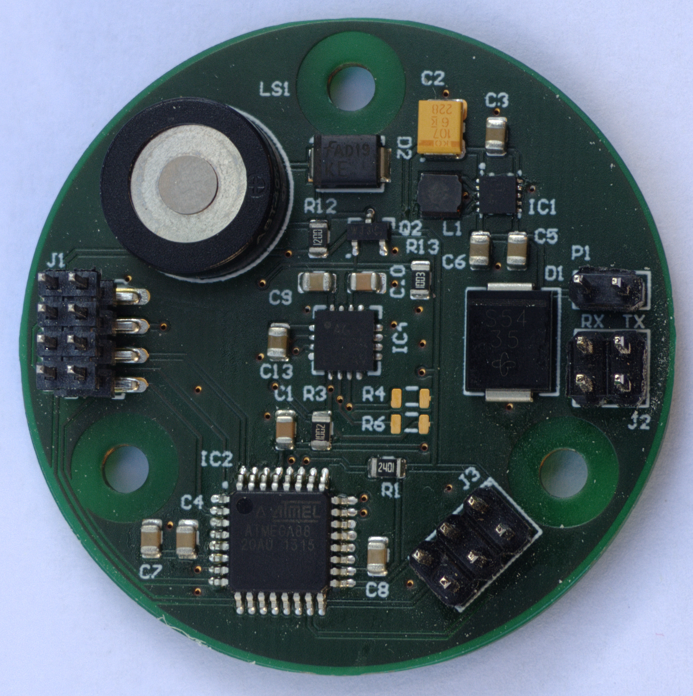
Control board
The control board’s “heart” is the 8 bit microcontroller ATmega88-20AU (IC2)
running at 1 MHz. A L3GD20 gyroscope (IC4) and LIS302DL accelerometer (IC3,
on the bottom side), both made by ST, are used to detect gestures. They are
connected to the microcontroller through the I2C bus, whose pullups
are R1 (SDA) and R2 (SCL). There’s also two interrupt lines per sensor
connected to the CPU (INTACC and INTGYRO). The pullups R4, R6, R8 and R10 for
these signals are not equipped, because the microcontroller’s IO pins has
internal configurable pullups.
A Texas Instruments buck boost, TPS63031 (IC1), converts 1.8–4.5 V input
voltage to 3.3 V output voltage that powers all components. Since there does
not seem to be any internal protection circuitry diode D1 protects it from
batteries attached with reverse polarity.
Other notable components are pin header for LEDs (J1), power (P1),
programmer (J3) and UART (J2), as well as the speaker (LS1).
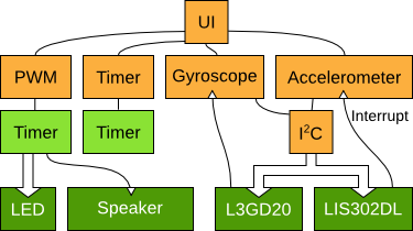
Software
The software (local repository), like most of embedded code, consists of
a number of state machines. The user interface (UI) is biggest one. It controls
the whole device by accessing the drivers for PWM, timer, gyroscope and
accelerometer, which provide a thin layer of abstraction and should be
reusable. Interrupts are handled in asynchronous fashion: They set a flag and
wake up the main loop that decides what to do next.
Gesture recognition
One goal was gesture recognition without polling the sensors. That does not
work for the spin gesture, which is not that bad, since its recognition is only
required in time selection mode. Thus the sensor can be switched off most of
the time. That’s not the case for the accelerometer, which is used to detect
flip and shake gestures, though. Fortunately the sensor comes with so-called
“free fall interrupts”, which trigger after the sensor readout exceeds or falls
below a programmed value for programmable time.
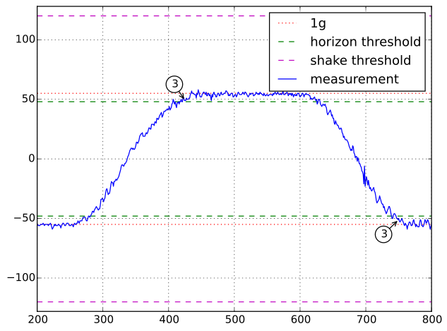
The flip gesture is pretty straight-forward. As soon as the the (absolute)
measured value rises over the horizon threshold for at least 150 ms an
interrupt is fired. It triggers a sensor readout to determine the actual
orientation. The horizon threshold is slightly below 1 g. The graph below shows
continuous sensor measurements for two slow flips:
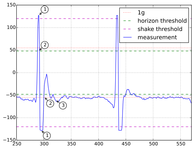
Shakes can be detected with a second high threshold. The sensor is configured
to map ±2 g to a signed char (-128 to 127) and the programmed threshold is
slightly below that value. In the following graph three events can be observed
(ignore the clipping at 1):
- The value raises above the shake threshold, triggers an interrupt and
increments the shake counter. A count of two corresponds to one shake
gesture.
- A flip gesture is not recognized, because peak 1 is shorter than 150 ms.
- Now a flip is detected and processed as described above
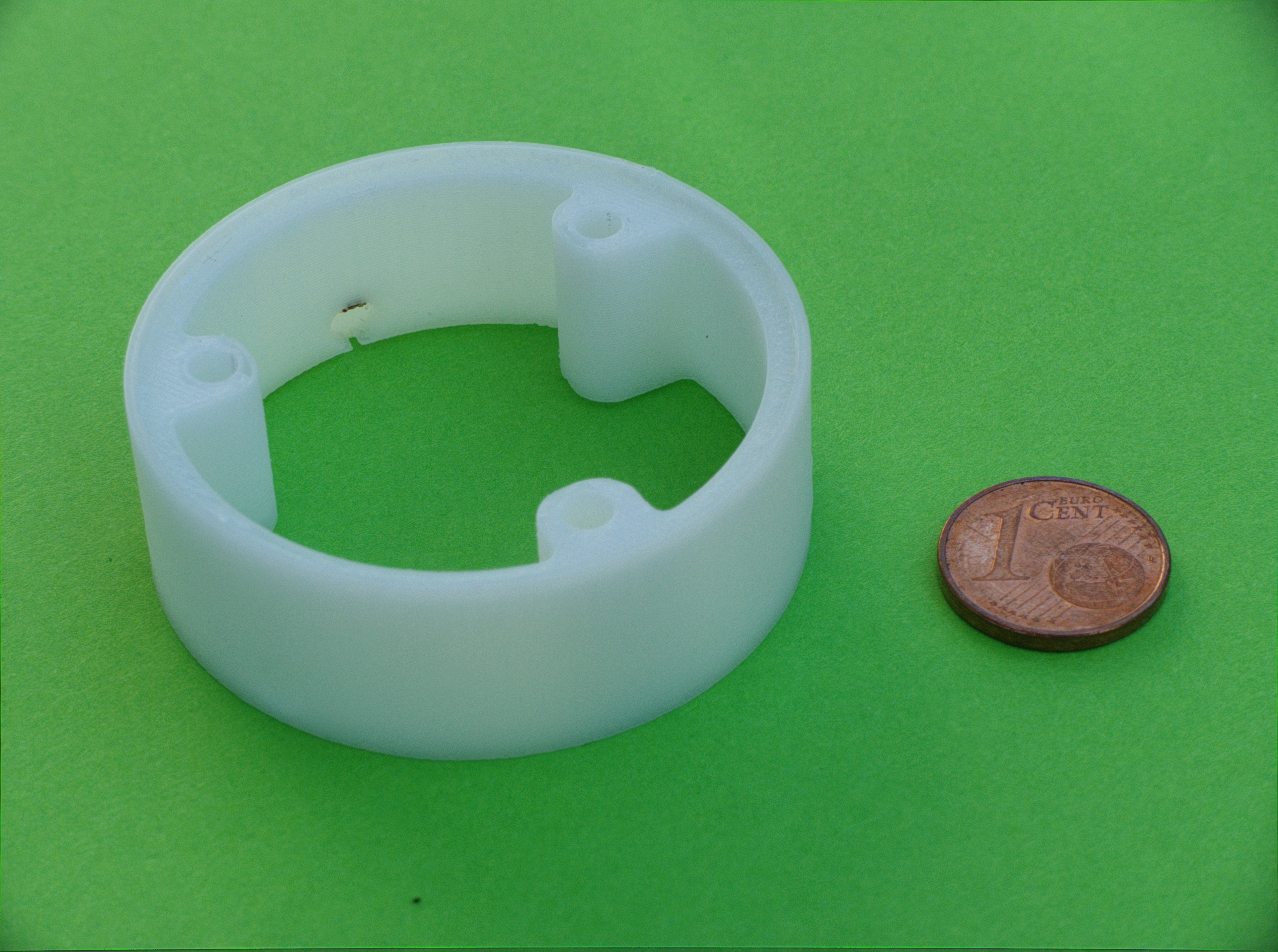
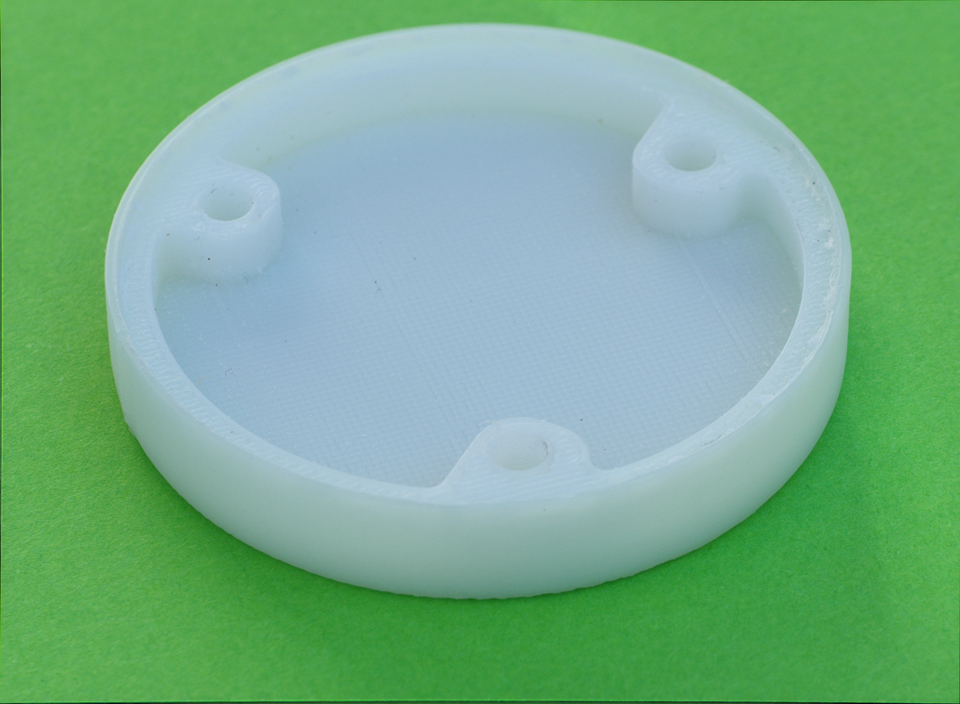
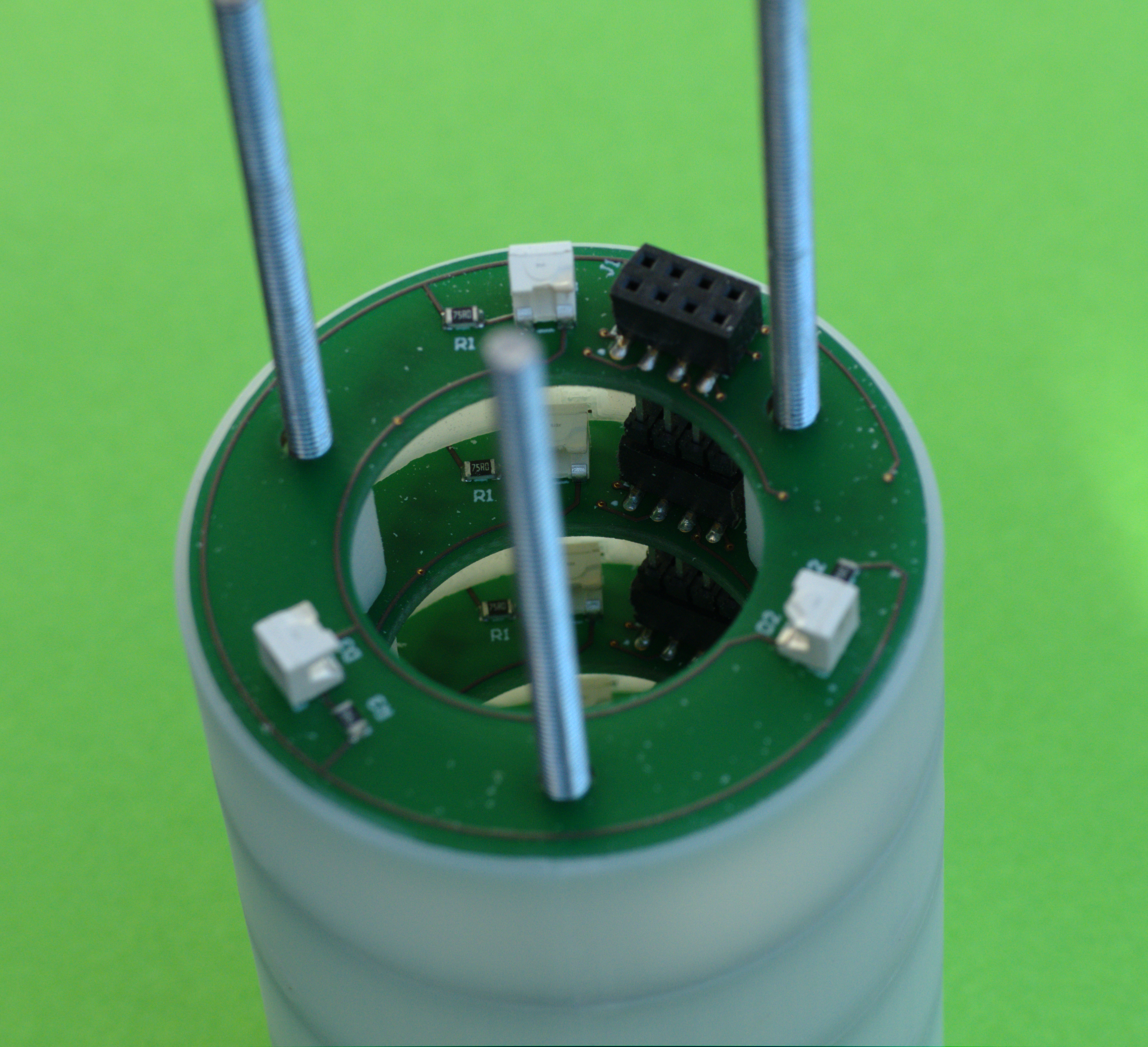
Casing
The casing has three parts: A ring that sits between the LED PCBs
(first picture) and a separate cap (second picture) for top and bottom (again,
see errata). They have been designed with SolidWorks and 3D printed in ABS
white. Design files are available here (signature). Three threaded rods
and six plastic nut (three on each side) hold everything in place, as seen in
the last two pictures. The final design’s height is 9.4 cm.
Cost
There are several aspects, and the first one is time. Designing the PCB took
about 50 hours. This is the first PCB I designed and I was not familiar with
Altium Designer before. Initial soldering with hot air took a whole work day
(about eight to nine hours). A few more hours can be added for replacing
components by hand, including the small buck-boost (QFN-10). Finally I spent
about 100 hours designing the software. That includes reading IC documentation,
getting familiar with embedded programming (my first embedded project) and
endless hours of debugging.
Next up, money. The table below was up-to-date in 2013/2014 and does not take
shipping into account. However prices include 19% VAT/GST.
| Part |
Quantity |
Cost [€] |
|---|
| PCB production (at PCB-POOL) |
1 |
130.35 |
| Casing (3D printed) |
1 |
32.14 |
| Gyroscope (L3GD20) |
1 |
11.01 |
| Accelerometer (LIS302DL) |
1 |
4.09 |
| Microcontroller (ATMEGA88-20AU) |
1 |
3.99 |
| Buck-Boost (TPS63031) |
1 |
3.36 |
| LED (LYA67K-J2M1-26) |
18 |
2.95 |
| Transistor (BSH103) |
6 |
2.47 |
| Capacitor (22 µF) |
5 |
2.20 |
| Transducer (ABT-407-RC) |
1 |
1.16 |
| Capacitor (100 µF) |
1 |
1.10 |
| Diode (SSC54-E3/57T) |
1 |
0.43 |
| Resistor (75 Ω) |
18 |
0.27 |
| Diode (SMBJ5V0A) |
1 |
0.25 |
| Inductor (NR3015T2R2M) |
1 |
0.21 |
| Resistor (100 kΩ) |
6 |
0.19 |
| Capacitor (100 nF) |
6 |
0.16 |
| Resistor (0 Ω) |
6 |
0.08 |
| Resistor (2.4 kΩ) |
2 |
0.08 |
| Capacitor (10 nF) |
1 |
0.02 |
| Resistor (120 Ω) |
1 |
0.01 |
| Total |
1 |
196.52 |
Several parts are missing in this table, including connectors for LED and
control boards.
Producing small quantities of PCBs is very expensive. With 100 units the price
for PCBs could be cut down to 5.70 € per device. The same holds true for other
components like sensors and ICs and I estimate for 100 devices the hardware can
be bought for 25–30 € each (without actual assembly and casing). That’s still a
pretty expensive hourglass.
Errata
The hourglass presented is a prototype and suffers from typical flaws that
could have been easily prevented at design time.
The board lacks markings for power supply +/- and a board revision. One of the
two ground pins on the UART pin header (J2) should have been a VCC pin. The
holes in the PCB are not equally spaced, i.e. they do not form a isosceles
triangle. Designing the case would have been easier if they did.
I used two separate sensors and found out MEMS modules with both, gyroscope and
accelerometer in one package, exist only after producing the PCBs. These
sensors are also less expensive than buying two separate devices, so it would
make sense to use those. Initially I ordered two TPS63030 instead of the
TPS63031. Obviously the device did not power up and I had to replace them.
After doing so the device still did not boot, because the reset resistor (R3)
and capacitor (C1) were too big. Replacing them with 10 kΩ and 10 nF
respectively worked.
Additionally there are unresolved issues regarding the design itself:
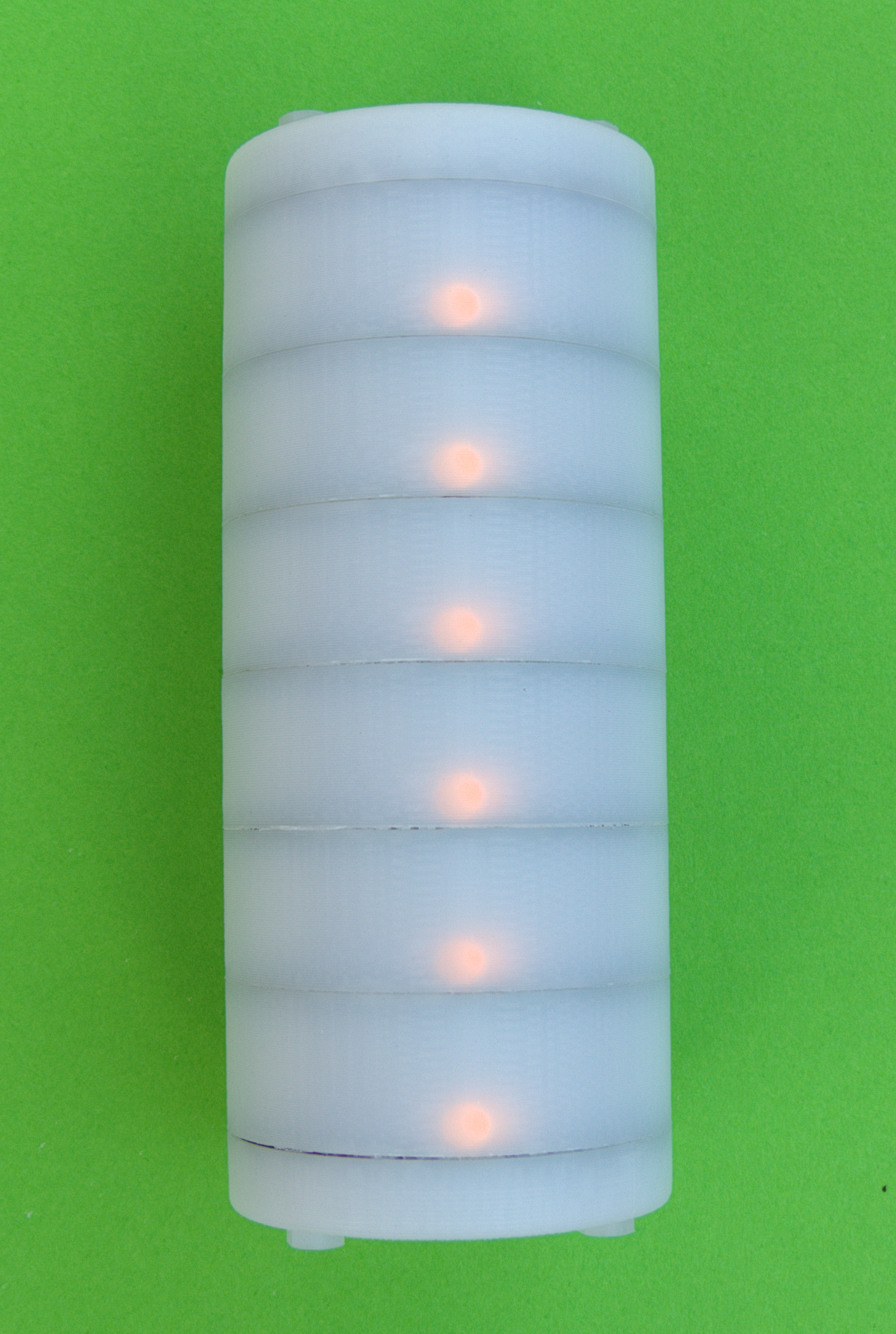
The initial idea was to illuminate the whole ring with three LEDs. As the
picture above clearly shows this goal was not achieved. Only a tiny spot of
the casing is bright, leaving everything else dark.
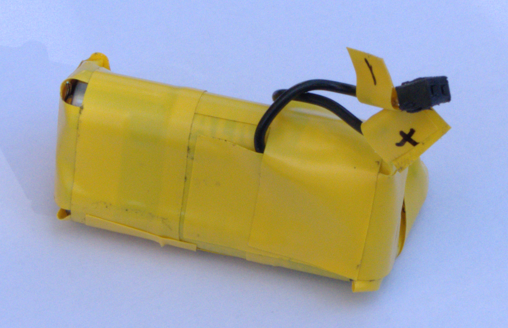
Also there is no battery solution yet. For programming I’ve been using an
external power supply, which is a little cubersome when testing gestures, but
works most of the time. Since the device was supposed to be battery powered I
also created a custom battery pack consisting of three AAA batteries, aluminum
foil and tape (see picture below). It fits perfectly inside ring hole, as
it was supposed to. However this is not a permanent solution. Commercially
available battery holder that fit don’t exists as far as I know, so a 3D
printed solution might be the last resort.
The prototype’s main problem is power usage, as the table below suggests.
| Idle |
3 mA |
0.010 VA |
| Timer |
60 mA |
0.196 VA |
| All LEDs |
393 mA |
1.268 VA |
The PWM implementation might not be ideal yet, but further optimizing it won’t
reduce the power usage significantly I believe. Compared to an LC display 18
LEDs will always use more power, which is the reason most battery powered
consumer electronics prefers the former.